


|

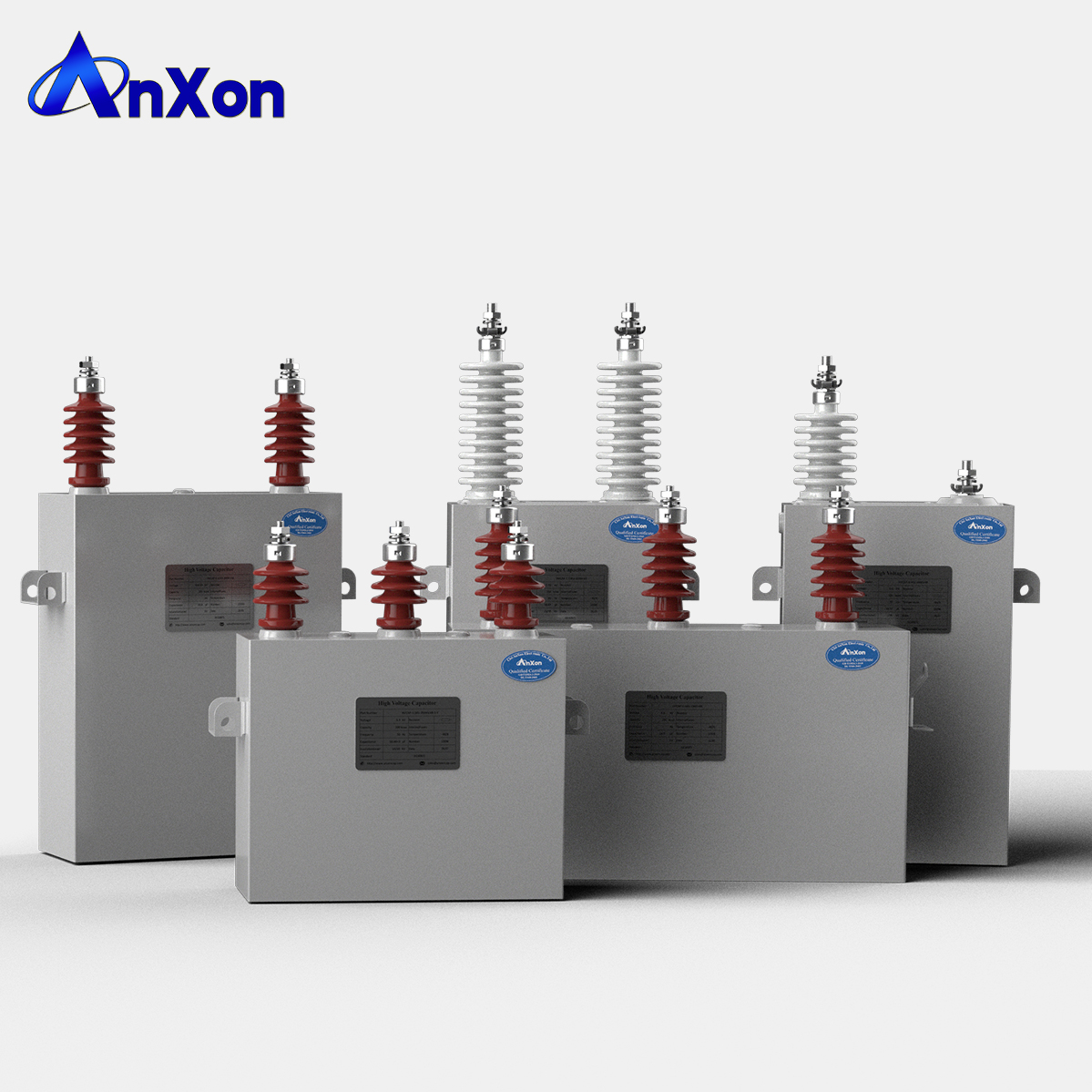
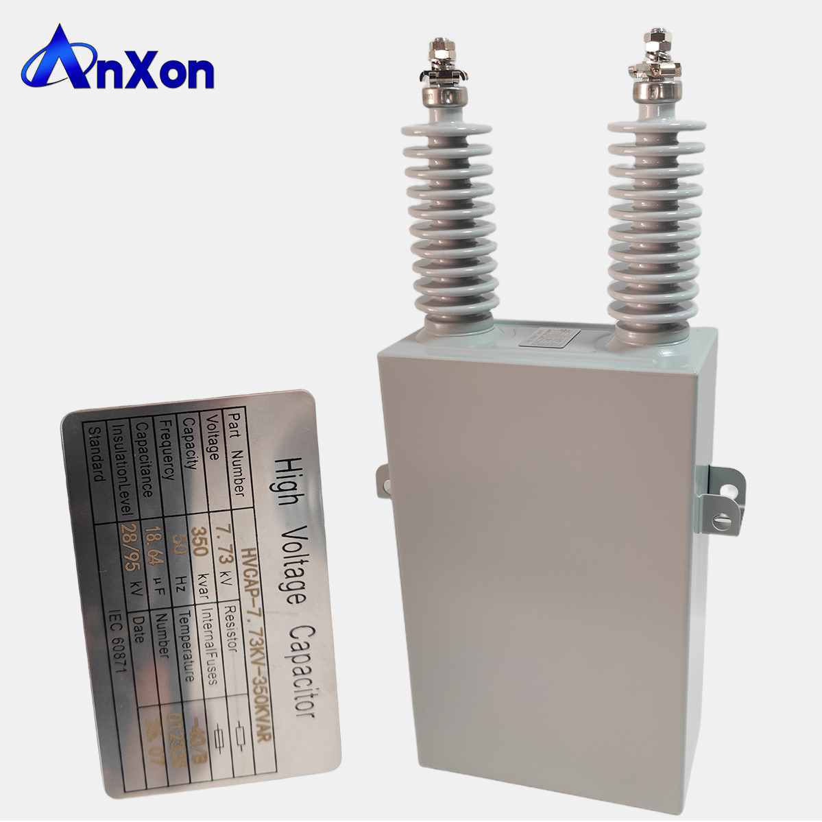
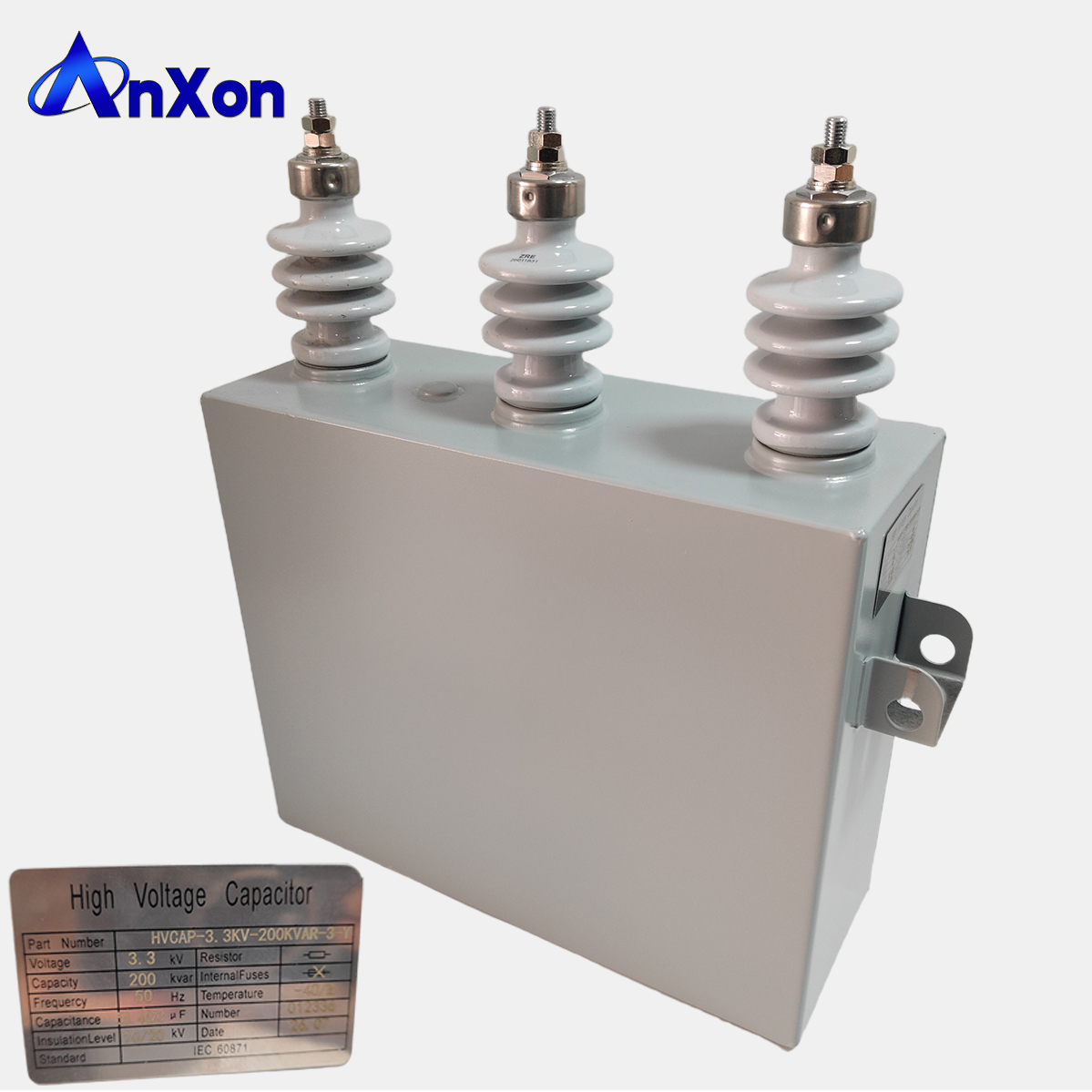
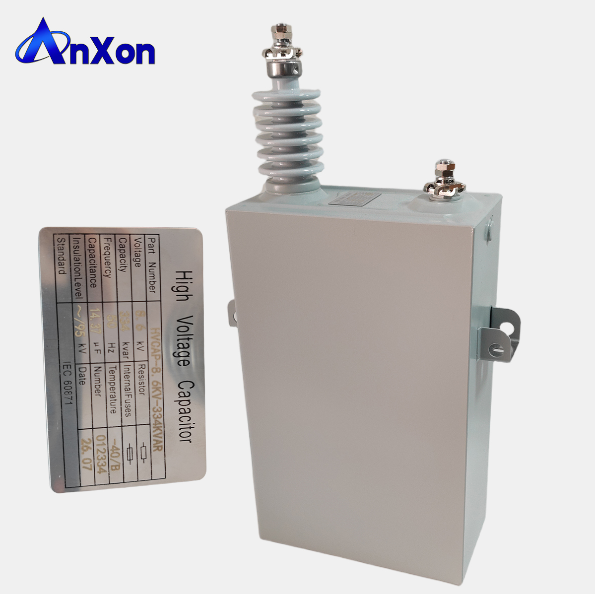
High-quality high-voltage capacitors, specifically designed for power transmission, distribution, and industrial power systems. Grid-verified ceramic material: electrical porcelain shed, with excellent high-voltage resistance and anti-pollution performance, widely used in global grid projects. Stable and durable: with a lifespan of 10-20 years in harsh industrial/grid environments, resistant to ultraviolet rays, temperature differences, and chemical corrosion. Global compliance: obtained IEC 60871 certification, fully compliant with grid standards in Europe, Asia, Africa, and other regions. We ensure reliable quality and timely delivery for our global customers.
We can provide a detailed specification sheet. Please note that dimensions and weight may vary according to your specific needs - we are happy to customize the product based on your specific requirements.
|
Technical data and specifications |
|
|
Reference standards |
GB/T 11024.1-2009 (IEC60871-1:2005.) |
|
Voltage range UN |
1.05; 3.15; 6.6/√3; 6.3: 10.5/√3: 10.5: 11/√3: 11/2; 11: 12/√3: 12/2: 12: 21/√3 : 22/√3:24/√3kV |
|
Var power QN |
50; 100; 150; 200; 300; 334; 400; 417; 500Kvar |
|
Tangent of loss angle tanδ |
At rated voltage and a temperature of 20°C, the tangent of the loss angle (tan δ) for all-film dielectric capacitors shall not exceed 0.0005. |
|
Capacitance tolerance |
The deviation of the measured capacitance from the rated value shall be within -5% to +5% of the rated value; for three-phase capacitors, the ratio of the maximum to the minimum capacitance measured between any two terminals shall not exceed 1.02. |
|
Voltage resistance: |
The inter-electrode of the capacitor should be able to withstand an AC voltage of 2.15 times or a DC voltage of 4.3 times the rated voltage for 10 seconds without breakdown or flashover; |
|
Overvoltage |
At 1.1 times the rated voltage, the duration should not exceed 12 hours per 24 hours; at 1.15 times the rated voltage, the duration should not exceed 30 minutes per 24 hours; at 1.2 times the rated voltage, the duration should not exceed 5 minutes; and at 1.3 times the rated voltage, the duration should not exceed 1 minute. |
|
Overcurrent |
The capacitor shall be capable of operating under a continuous overcurrent not exceeding 1.3 times the rated current, caused by fundamental overvoltage, harmonics, or a combination of both. For capacitors with an actual capacitance of up to 1.05 times the rated capacitance, the permissible continuous overcurrent is 1.37 times the rated current. |

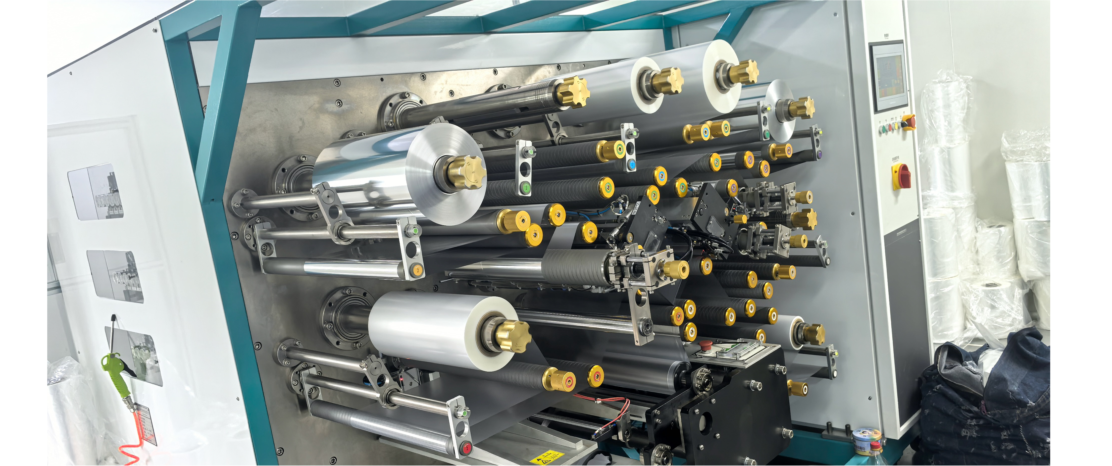
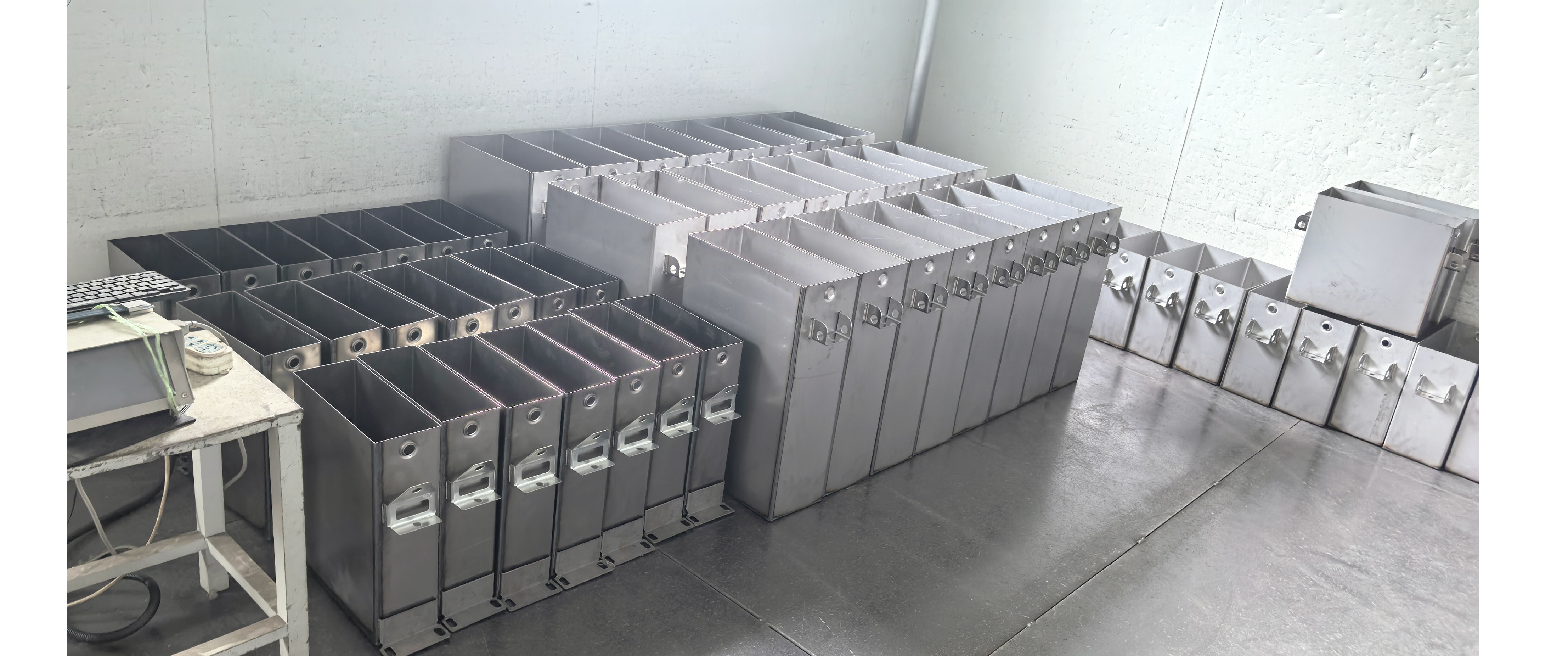
The capacitor consists of a case and a core. The case is made of thin steel plates sealed and welded together. The case is welded with a porcelain bushing for outgoing lines, and lifting lugs for installation are welded on both sides of the case wall, with a grounding bolt on one side. The capacitor core is made by stacking multiple components and insulating parts. The components are formed by winding and flattening two aluminum foils as plates with a film paper composite dielectric or a full film dielectric sandwiched in between. The components in the core are connected in a certain series or parallel manner to meet the requirements of different voltages and capacities. For capacitors with internal fuses, each component is connected in series with a fuse. When a component breaks down, the intact components connected in parallel to it discharge, causing the fuse to quickly melt and cut off the faulty component within milliseconds, allowing the capacitor to continue operating. Three-phase capacitors are connected in a star configuration. The liquid dielectric is used in the capacitor to impregnate the solid dielectric and fill the voids inside the capacitor. It has excellent electrical and physical properties and good compatibility with other materials in the capacitor.


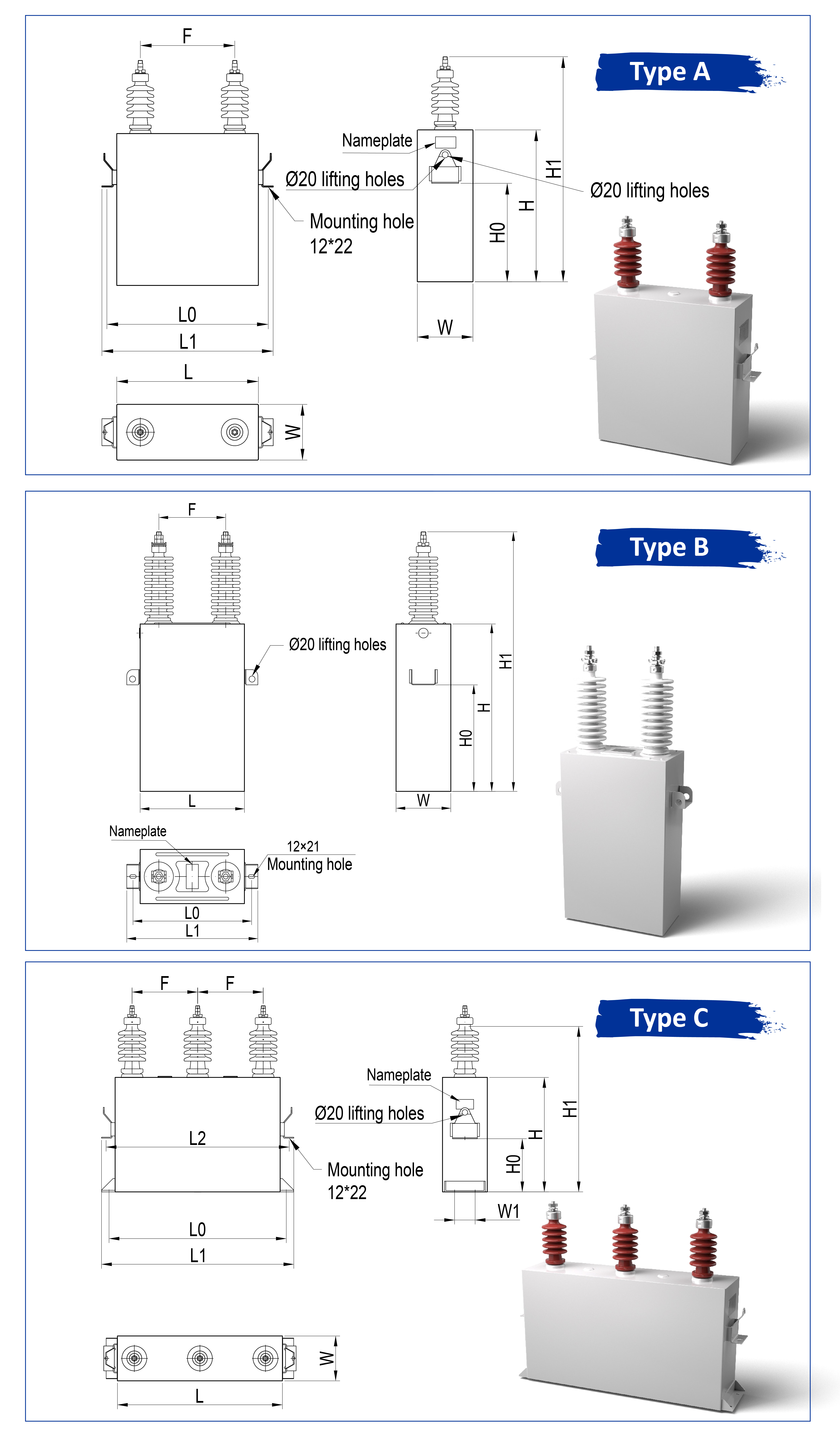 、
、
|
Part Number |
UN |
QN |
CN |
Size(mm) |
Wegith |
Type |
|||||||||
|
KV |
kvar |
μF |
L0 |
L |
L1 |
L2 |
H0 |
H |
H1 |
F |
W |
W1 |
kg |
||
|
BFM1.05-50-1W |
1.05 |
50 |
144.4 |
370 |
310 |
400 |
|
150 |
280 |
400 |
200 |
120 |
|
17 |
A |
|
BFM1.05-100-1W |
1.05 |
100 |
288.8 |
440 |
380 |
470 |
|
230 |
360 |
480 |
250 |
140 |
|
27 |
A |
|
BFM3.15-50-1W |
3.15 |
50 |
16 |
370 |
310 |
400 |
|
150 |
280 |
400 |
200 |
110 |
|
17 |
A |
|
BFM3.15-100-1W |
3.15 |
100 |
32.1 |
440 |
380 |
470 |
|
230 |
360 |
480 |
250 |
120 |
|
24 |
A |
|
BFM6.6/√3-50-1W |
6.6/√3 |
50 |
11 |
370 |
310 |
400 |
|
150 |
280 |
490 |
200 |
110 |
|
17 |
A |
|
BFM6.6/√3-100-1W |
6.6/√3 |
100 |
21.9 |
440 |
380 |
470 |
|
230 |
360 |
570 |
250 |
120 |
|
27 |
A |
|
BFM6.6/√3-150-1W |
6.6/√3 |
150 |
32.9 |
480 |
420 |
510 |
|
230 |
360 |
570 |
280 |
165 |
|
37 |
A |
|
BFM6.6/√3-200-1W |
6.6/√3 |
200 |
43.8 |
560 |
500 |
590 |
|
230 |
360 |
570 |
320 |
165 |
|
43 |
A |
|
BAM6.6/√3-200-1W |
6.6/√3 |
200 |
43.8 |
443 |
383 |
473 |
|
300 |
430 |
670 |
250 |
163 |
|
41 |
B |
|
BAM6.6/√3-300-1W |
6.6/√3 |
300 |
65.8 |
443 |
383 |
473 |
|
470 |
600 |
840 |
250 |
163 |
|
54 |
B |
|
BAM6.6/√3-334-1W |
6.6/√3 |
334 |
73.2 |
443 |
383 |
473 |
|
520 |
650 |
890 |
250 |
163 |
|
59 |
B |
|
BAM6.6/√3-400-1W |
6.6/√3 |
400 |
87.7 |
443 |
383 |
473 |
|
570 |
700 |
940 |
250 |
179 |
|
72 |
B |
|
BAM6.6/√3-417-1W |
6.6/√3 |
417 |
91.4 |
443 |
383 |
473 |
|
600 |
730 |
970 |
250 |
179 |
|
75 |
B |
|
BAM6.6/√3-500-1W |
6.6/√3 |
500 |
109.6 |
443 |
383 |
473 |
|
600 |
850 |
1090 |
250 |
179 |
|
86 |
B |
|
BFM6.3-50-1W |
6.3 |
50 |
4.01 |
370 |
310 |
400 |
|
150 |
280 |
490 |
200 |
110 |
|
17 |
A |
|
BFM6.3-100-1W |
6.3 |
100 |
8.02 |
440 |
380 |
470 |
|
230 |
360 |
570 |
250 |
120 |
|
27 |
A |
|
BFM6.3-150-1W |
6.3 |
150 |
12 |
480 |
420 |
510 |
|
230 |
360 |
570 |
280 |
165 |
|
37 |
A |
|
BFM6.3-200-1W |
6.3 |
200 |
16 |
560 |
500 |
590 |
|
230 |
360 |
570 |
320 |
165 |
|
43 |
A |
|
BAM6.3-200-1W |
6.3 |
200 |
16 |
443 |
383 |
473 |
|
300 |
430 |
670 |
250 |
163 |
|
41 |
B |
|
BAM6.3-300-1W |
6.3 |
300 |
24.1 |
443 |
383 |
473 |
|
470 |
600 |
840 |
250 |
163 |
|
54 |
B |
|
BAM6.3-334-1W |
6.3 |
334 |
26.8 |
443 |
383 |
473 |
|
520 |
650 |
890 |
250 |
163 |
|
59 |
B |
|
BAM6.3-400-1W |
6.3 |
400 |
32.1 |
443 |
383 |
473 |
|
570 |
700 |
940 |
250 |
179 |
|
72 |
B |
|
BAM6.3-417-1W |
6.3 |
417 |
33.4 |
443 |
383 |
473 |
|
600 |
730 |
970 |
250 |
179 |
|
75 |
B |
|
BAM10.5/√3-50-1W |
6.3 |
500 |
40.1 |
443 |
383 |
473 |
|
600 |
850 |
1090 |
250 |
179 |
|
86 |
B |
|
BFM10.5/√3-50-1W |
10.5/√3 |
50 |
4.33 |
370 |
310 |
400 |
|
150 |
280 |
490 |
200 |
110 |
|
17 |
A |
|
BFM10.5/√3-100-1W |
10.5/√3 |
100 |
8.66 |
440 |
380 |
470 |
|
230 |
360 |
610 |
250 |
120 |
|
27 |
A |

a. The altitude at the installation site shall not exceed 1,000 m (customized versions are available for installations above this altitude).
b. The ambient temperature at the installation site shall be between -40°C and +45°C.
c. The installation site shall be free from severe mechanical vibration, harmful gases or vapors, and conductive or explosive dust.
d. Before the capacitor is put into operation, the residual voltage across its terminals shall not exceed 10% of the rated voltage.
e. If the capacitor is subject to any special operating conditions—such as high relative humidity, rapid mold growth, corrosive atmosphere, pollution, altitude exceeding 1,000 m, or seismic activity—the purchaser shall notify the company to agree upon the product type and any necessary special preventive measures.

These capacitors are designed for installation at altitudes up to 1500 meters. For installations exceeding this height, we offer special versions tailored to specific site conditions. They operate reliably within a temperature range of -40°C to +55°C and should be installed in a clean, vibration-free environment, avoiding harmful gases, vapors, or explosive dust.

1. Rated voltage.
2. Rated capacity.
3 . Rated frequency.
4 . Number of phases.
5 . Protection method (internal fuse or external fuse) 11.6 Usage location: indoor or outdoor.
6 . Wiring method: △ or Y.
7 . Is there a discharge resistor installed inside.
8 . Other special requirements.